(Shamelessly copied from KimDN’s post on KTM Talk)
For those of you not wanting to do a complete engine swap, here is how Kenny and I installed a kickstart lever onto my Freeride engine. Sorry, I’m horrible at taking pictures during the process so I don’t have any. I will try to put up pictures from a guy on the German Facebook Freeride page, but they aren’t very detailed.
I got most of my parts used to save some $.
The toughest part is drilling/reaming two holes from 14mm to 17mm; one for the idler gear shaft and one for the kick gear shaft. That was tricky but Kenny is s smart MF so he figured out how to do it with the engine in his drill press. The German guys do it with the engine in the bike, but I think that is crazy. In addition to enlarging the two holes I mentioned, you also have to tap a few existing holes. The frame will have to be cut/machined away a bit for clearance for the kickstart lever to move.
You will need all kickstart parts from a 2015 era 250/300
You will need the inner clutch cover from 2005 – 2016 250/300 Part # 54830001244 (used ones are relatively easy to find on ebay). I used a new water pump impeller kit part # 5483505510 and the centrifugal timer part # 54837050044 which turns the impeller. You might be able to find a way to make the Freeride impeller setup work, but I wasn’t sure how to do that safely so I just went with the 250/300 timer.
Kenny made a piece that has the barb fitting for the crankcase vent hose, located at the spot on the inner clutch cover which would normally have the powervalve rod going through. He also found a cover for where the powervalve adjuster would be. I’ll edit this post or elaborate more on that when I find out which cover he sourced for that.
Remove the Freeride inner clutch cover and clutch basket. You’ll see the hole where the idler gear bushing pin goes, but it isn’t big enough. You have to enlarge it to 17mm, the size of the bushing pin. You’ll also have to tap the small hole in the center of that 17mm hole with a 5×1.00mm tap. If you notice in the diagram above, the idler gear bushing pin is pictured next to the idler gear #24; the part # is on the crankcase screen along with the bolt that holds it in place.
The other hole to enlarge to 17mm is the kickstart shaft hole. You’ll also have to tap the holes for the #61 bolts, and for the #60 bolt with 5×1.00mm tap again.
Once you have the idler gear bushing and kick shaft holes enlarged to 17mm, and the aforementioned holes tapped, you can install the kickstart parts just as you would on a 250/300.
Last thing to do is to cut a section of the aluminum frame piece so the kicker can rotate. I’m currently using the kick lever from a 2017 300xc, which is a lot smaller than the kick lever pictured above (2015ish). The newer style lever is much lighter and requires less material to be removed from the frame; but it is a lot more difficult to get a good kick. If you are planning on kicking only as a last resort, I would say to use the new style kicker. But, if you are planning on kicking on a regular basis, I’d use the bigger older style. I kicked all day yesterday with the newer lever and it sucked.
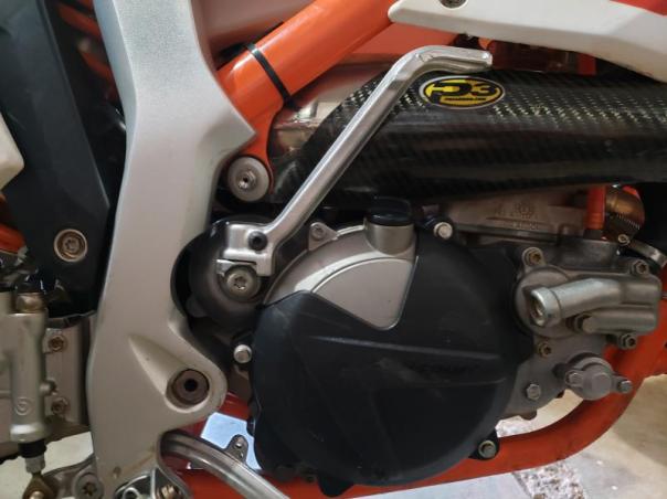
Here’s a picture of my bike now. Notice the frame cutout, the powervalve cover, and the powervalve vent. And the cool titanium bolt holding the pipe 
The cases are basically the same as the 250/300xcw. They just have not been ‘completed’. All the holes are there that need to be tapped and they are all plenty deep. The idler gear hole depth problem is only on 2017 bikes. For the holes you have to enlarge, you need to enlarge them as deep as the existing holes are. You need to tape everything up to keep shavings out, but that is easy. The idler gear shaft cannot be machined down, it is too tough of a metal (we tried).
If you use the small kicker like I do, it isn’t much frame material removed. It is sort of braced in the back so that helps. Kenny’s frame is cut out for the bigger kicker, and it has had no problems over the last few years. I doubt it will.
Water Pump Impeller
They are in the Exhaust Control diagram. Numbers 31 and 99. 31 is the power valve timer, but it also serves as the water pump gear. You might be able to figure out how to make your Freeride water pump gear work, but I already had the PV timer so I didn’t bother.